 |
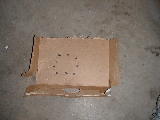
Prepare a crude drawing of your housing cover on the
cardboard. Use an awl to punch holes about where the bolts are
located. If you wish, use the replacement gasket as a template,
draw it out and then punch the holes. This helps insure the proper
bolts get returned to the proper hole on reassembly. |
|
|
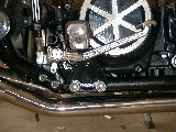
Place your bike on the side stand. This will
allow all of the oil to run to the opposite side of the crank
case. Remove the right side foot peg. There will be a spring
that connects the brake lever to the brake light switch. Once the
two fasteners for the peg are removed, maneuver the assembly to
disconnect the spring.
|
|
|
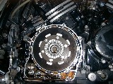
Remove the bolts holding the clutch cover on. Make
note of the bolt that holds the rear brake switch. Draw
it on your cardboard for easy assembly. The picture on the left
allows you to see where all of the bolts are located.
You may have some resistance removing the cover from the gasket
"welding" itself to the cases, or possibly Yamabond. It
is best to have a new gasket. Do it right the first time.
|
|
|
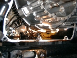
Here's a side note on the missing fifth gear. Behind
the clutch housing is the shift drum. By pushing on pins, the drum
rotates like a turret to select the next/previous gear. In this
instance, a simple adjustment of the pin retainer was
necessary. The retainer had bent, causing the turret to get
hung up on the shifting arm.
Complete repair would have consisted of removing the clutch boss and
replacing the selector. An updated version is available from
Yamaha. Some
help in removing the clutch boss may be found here.
|
|

|
Back to servicing the clutch. Six bolts used to hold
the clutch spring retainer are removed. Loosen each evenly to prevent uneven stress on any
one of the retaining fasteners. |
|
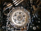
|
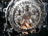
Once the retainer ring and spring are removed, there is a
spring washer and the pressure plate left. These pull straight off
with no trouble. The spring washer here is held on by the oil. |
 |
Removal of the clutch and friction plates is
straightforward. Use a 90 degree pick or bent paper clip to help
slide the plates forward for removal. After seven friction plates
and six clutch plates are removed, there is a retaining wire that must
be removed. A pair of needle nose works ok here. Don't
mangle the wire if you are not doing the Double "D", or plan
to return things to stock later.
One thing to note here is there is usually no wear on this last
friction plate and clutch plate. Removal is only necessary to do
the Double "D" or complete clutch replacement. |
 |
Once the wire is removed, there is another clutch plate, a
half friction plate, clutch boss spring and spring seat. This
picture shows the difference between the half friction plate and full
one. The I.D. is larger on the half disk. |
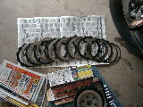 |
Here's the complete layout of the parts. Only thing
not shown is the spring, spring seat and pressure plate.
When doing the Double "D", the wire, clutch boss spring and
spring seat are discarded. The half friction disk is replaced with
a full disk.
The stock setup uses all the same friction disks except for the half
disk located behind the wire.
|
 |
Inspect the plates for bluing or warping. A slipping
clutch can generate a lot of heat, causing discoloration. This
clutch has obviously been through a lot. |
 |
Reassembly is relatively easy. Stock setup starts
with the clutch boss spring seat and clutch boss spring, followed by the
half friction plate, a clutch plate and the piano wire. |
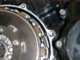 |
There are some things to note here:
*There is a rounded edge and sharp edge on the clutch plates from the
manufacturing process. Be sure all clutch plates are facing the
same direction. It is said direction does not matter as long as
all are the same. I choose to have the rounded edge out.
*The friction plates are marked on two ears. A single cut on
one ear, and a double cut 180 degrees from there. All similar
friction plate ears should line up with the indicator of the clutch
boss. If clutch drag is noticed after reassembly, Yamaha
recommends to rotate all friction disks 180 degrees with the friction
plate alignment indicator on the clutch boss.
*Coat all friction plates with fresh oil before assembly. This
will help prevent excessive wear the first time the new clutch is
engaged.
|
 |
Alternate friction plate, clutch plate after the wire and
you should end up with a friction plate out front. Then install
the pressure plate, aligning the mark on the pressure plate to the mark
on the clutch boss. Install the clutch spring seat. |
 |
Install the clutch spring (both springs if doing the
Double "D") and the spring retainer. Use blue Loctite on
the clutch spring retainer fasteners.
Note: Tighten each fastener a little at a time as to not stress an
individual bolt. Yamaha recommends 5.8 ft/lbs (8Nm) of torque for
these, however use your own judgment. I recommend firm.
Removing a broken bolt from the clutch boss is not how to spend the
weekend.
|
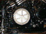 |
Reinstall the clutch housing cover and brake light
switch. If you placed the cover screws into the cardboard,
identification should be easy. Yamaha says crankcase cover torque
is 10Nm (7.2 ft/lb.)
*Use a new gasket if possible. Successful sealing is possible
without the use of a gasket maker material (Yamabond). Be sure
both surfaces are absolutely clean. This is the key to a dry
garage floor. Double check no gasket material is floating around
inside the clutch or housing as well. You may choose to clean the
gasket off prior to disassembly of the clutch plates so nothing falls
into your new setup. |
 |
Reinstall the foot peg after reconnecting the brake switch
spring. Yamaha says 23Nm (17 ft/lb).
Double check your oil level and give her a spin.
|
|
There are no warranties as to the accuracy
of this information. This may or may not work for you. If
you have any doubt, seek a trained Yamaha service professional. |

![]()