|
Carbuerator Pictures (*.jpg) Parts -
Page 4
1997 Canadian Vmax JYA2LTN
These
pictures were taken to help me re-assemble.
Some part names had to be invented.
Bob Walsh VMOA 2469 |
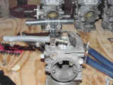 |
Fuelline
- the relative positioning of the hoses that join the carburetors.
Note that the black hose is longer on one side than the other. |
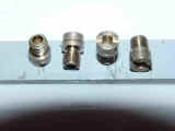 |
PAJ1,
PAJ1a
- the same jets, two pictures. |
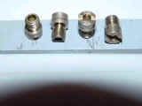 |
PAJ1,
PAJ1a
- the same jets, two pictures. |
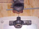 |
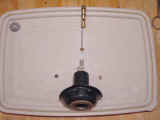
Piston1
- the piston valve relative to it's chamber.
On the bar to the left is the o-ring from the lower left of the
chamber rim. On the bar to the right are PAJ2 and the idle screw.
The piston valve spring goes into the hollow of the piston valve,
as at the bottom of this picture. (It
was omitted from the picture because it made the other parts look too
small, IMHO.) Piston valve
diaphragms - these may be stuck to the carb body but can be loosened
similar to the coasting enrichment diaphragms but first gently push the
needle in the carb throat towards the piston valve until the diaphragm
is in its natural "umbrella" shape.
See piston1, 2 & 3.jpg.
Use your fingers to hold the diaphragm ring and loosen as per
coasting enrichment diaphragms. |
 |
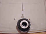
Piston2
- The piston valve parts disassembled in relative orientation to each
other. The needle drops
point first into the diaphragm end with the orange ring.
There is a small alignment pin on the ring around the needle that
must fit into it's hole in the piston valve before the washer, spring
and screw are dropped in (in that order) or you will not be able to
start the screw in it's hole and even then it's an exercise in patience.
Actually only the spring will fairly easily "drop in".
The washer and screw require a light touch and some coaxing. |
 |
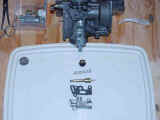
Piston3
- A different shot of the diaphragm to show the tab that must be aligned
for proper fitment of the diaphragm to the piston valve chamber.
This is very easy to do if the diaphragm is positioned as shown
in piston1, 2 and 3.jpg, in it's natural "umbrella" shape, and
kept that way by holding the needle in the carburetor throat with two
fingers while compressing the piston valve spring with the piston valve
chamber cover with the other. Ensure
the piston valve spring is outside all 3 legs in the center of the
chamber cover. Once the
cover is in position you can let the needle slide into position. |
 |
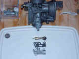
Starter1
- the starter plunger assembly and relative to it's position on the
carb. The starter plunger rods and levers (not seen here, see carbsup
& down pics) go in the front first (carbs 2 & 4) through to the
back, with the "choke" lever by #2. The starter levers are slid on as you push the rods in.
Note that #2 is different, see starterpuller.jpg and notes.
Make sure the bushings are in place also, see
startershaftbushings pic and notes. |
 |
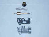
Starter2
- the plunger itself disassembled. |
 |
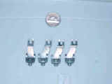
Starter3
- a close-up of these parts. |
 |
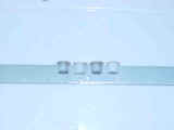
Starterpuller
- the levers that pull on the starter plungers which are attached to the
starter leaver rods (1 per 2 carbs) and activated by pushing down on the
lever by carb #2 (which is marked "Choke" but is not a choke).
More importantly note that 3 of these are the same but the one
for carb #2 is different. |
 |
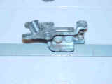
Startershaftbushings
- these can be found rolling around on your work table after removing
the starter leaver rods. If
your lucky enough to find one in place then you'll know that they go in
the lowest round hole on the right of each carb (vacuum chamber on a
flat surface, carb bottom towards you), which can be seen in
carbapart.jpg on the upper right and lower left carbs.
The other 2 carbs show the opposite side of the same hole that
does not have a bushing. |
 |
Throttlereturnbracket
- the cable goes through
this bracket to the inside of the connecting pulley. |
| |
|
Other
Notes On Disassembly
Throttle
pull cable (with adjusting nut) - cable goes through it's bracket on
carb #2 to the outside of the connecting pulley.
See carbsup & down pic's.
Throttle
pull bracket - this attaches to the carb #2 coasting enrichment cover,
per carbsup1.jpg
Top
brackets - these come off before / go on after the bottom brackets.
The idle adjust goes on carbs #1 & #2.
When
soaking the carb bodies in solvent for cleaning, the carb numbers as
seen in the carbsup pics were washed off!
So, the pictures already have proved their worth to me.
I hope they help someone else.
END/rjw
Sept. 12, 2003 |

![]()